 Bob's
MG Midget Website
Bob's
MG Midget Website| Bob's
MG Midget Website |
| A 5 Speed Gearbox Conversion | |||||||||||||||||||||||||||
The gearing on a Midget was always a sore point. All models were terribly undergeared and in the age of fast motorways it now suffers even more from poor economy and over-revving which can lead to overheating and engine failure. There are many ways you can assist the poor gearing including high ratio diffs, overdrive boxes and 5 speed conversions. As the old 4 speed box is now very inefficient by modern standards, the overdrive version from a Spitfire would be no quieter nor any more efficient. A box from a Toyota 180B is very hard to come by now so the most obvious (and most plentiful) choice is a Ford Type 9 from a Sierra/Capri/Granada 1.6 or 2.0. Once the choice was made, I acquired a second hand box and a spare 1500 bellhousing along with a conversion adapter plate to mate the two. Out of pure coincidence there was an old stock Avenger centre plate went on eBay the same day as I got the adapter plate. I purchased a propshaft and a speedo cable from Frontline - it was cheaper than getting them made up. All other bits and pieces I picked up as the project went on. The total bill was as follows:
Below is a short overview in pictures of my conversion as it took place. Much help was provided by James Mather (see www.the-wizardsden.com) who designed and cast the adapter plate and he deserves all of the credit for the inspiration for the conversion.
Unfortunately, I did not take any more pictures than these and remember, this is only my take on the conversion. You will get much more useful information on the process from James but I hope that what is here will give you the inspiration to do it. If I can finish the job, it proves it is not too hard and the car drives so much better on a motorway because of it. |
 |
Adapter
Plate Here I have shown the adapter plate between the bellhousing and the gearbox. This was a casting made up by James Mather as an alternative to the commercially available adapters sold at ridiculous prices. James will even do all of the machining on the plate for the bolt recesses (see www.the-wizardsden.com). |
|
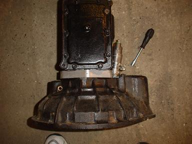 |
The
Adapter Here I have shown the adapter plate between the bellhousing and the gearbox. It is bolted up to the bellhousing using allen bolts and the original Ford bolts. It is such a simple looking conversion it almost looks like the unit was made this way. |
|
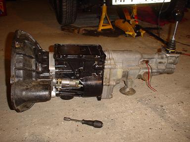 |
5
Speed Conversion In this picture you can see the completed gearbox conversion assembly. You can easily make out the clutch slave bracket and adjuster/clamp. Also in the picture is the reverse switch wiring soldered onto the sierra switch. This was an easy connection as all I had to do was solder a couple of bullets connectors on the other end and it connected straight into the original loom. The modified gearlever lever was made from a Sierra lever that had the centre section cut out then the two halves reconnected by tapping each end and connecting together with a bit of 5/16" UNF studding. It works really well now and allows for very quick changes without too much throw. |
|
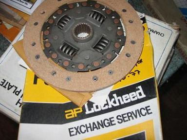 |
Clutch
Plate Although the outer cover plate is kept as standard, the inner or friction plate is replaced with one of these. It is from a Hillman Avenger 1500 which is roughly the correct size for the flywheel but more importantly, has the correct splines to fit the Ford gearbox. The outer diameter is about 5mm larger than it should be but this does actually fit in and soon beds in to the shape of the clutch. |
|
 |
Clutch
Slave This method of clamping the slave on allows the unit to be easily adjusted using a 10mm socket on a manual driver. The purpose built slave bracket is bolted up at a slight angle to clear the box. the bracket is made up of a bit of 40mm steel tube with a couple of tags welded on to bolt onto the bellhousing. The clutch slave is adjusted and fixed in place using a stainless steel exhaust clamp. It was supposed to be a temporary answer but was so practical and worked so well it was left as is. |
|
 |
Attack
the bugger Fitting the conversion in the car need some modification to the gearbox tunnel, so I attacked with a grinder. I needed to take out about 8 inches of crossmember and a bit of the floor pan. If you are wary of seriously modifying your car it is scary but necessary to continue. It didn't take much to hack it out and support it with some packaged 20mm box section tube. |
|
 |
The
missing bit This shows the bit that was cut out looking back from the engine bay. As you can see, the floor pan has a large plate missing. The box section used to go straight across but was sectioned out and the boxes reinforced with 20mm tube welded together. This reinforcement box section was hammered into the holes. Plates were then welded over the ends to keep the muck and grease out of the metal after applying some waxoil to the holes. The bare metal was then treated to a liberal coating of red oxide primer. this has got to be the most difficult place to weld when the bottom of the car is only 12 inches from the floor. Well, that's my excuse for the crap welding! |
|
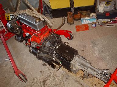 |
Ready
to go Once the clutch has been modified using the Avenger centre plate the gearbox can be bolted back up to the engine ready to put back in the car. Here you can see the complete assembly ready to go back in. At this stage it's a bit of a worry really when you have no idea whether it is going to fit. However, it did go in with plenty of space to spare. In fact it is far easier to get in than the standard box due to the enlarged tunnel. |
|
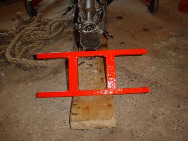 |
The
new crossmember As I cut the box section out of the car there is now nothing left to support the centre of the box. Here you can see a H section made up to bolt under the car. The original rubber Sierra gearbox mount fits into the centre and the the complete assembly then bolts on. two of the legs bolt right throught the reinforced box sections and the other two through the floor next to the gearbox tunnel. |
|
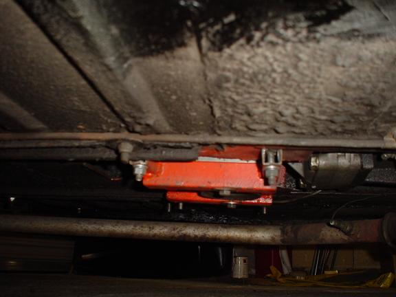 |
Undercarriage Here you can see the new crossmember bolted up under the car holding the box in place. You can just make out the original mounting. It is really about 30mm lower than it should be and the air filter just touches the inner wing as a result. This causes a little vibration when accellerating hard but since the K&N will be going soon perhaps it will cure this problem. |
|
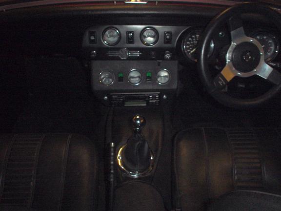 |
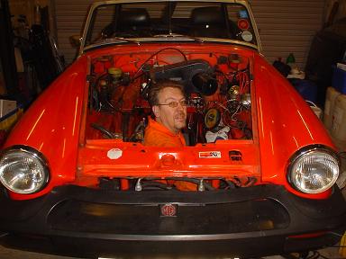
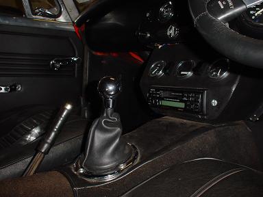
Cockpit Well, I don't know about you but I think that the new look of the cockpit looks quite smart. Everything is spaced out nicely and the gear lever falls just in the right place for quick changes. The chrome surround and knob from a MGB looks the part and fits in with the black/chrome look that I have kept in the car. Because the hole was in the wrong place, the centre section of the tunnel carpet was replaced using a piece of vinyl from my old roof. Crude maybe, but it looks OK until I get the interior retrimmed fully. |
|
 |
Gear
lever The new location for the lever really, I mean REALLY, makes a difference to the comfort and appearance in the car. It falls into the hand much better and you can see that it gives far more space to get cassettes and CD's in and out as well as allowing you to see the facia of the stereo unit. |
|
Update 10/04/05 A couple of modifications have been made to the original installation in terms of the crossmember mount and the speedo drive. These were to make the whole job a great deal more efficient. |
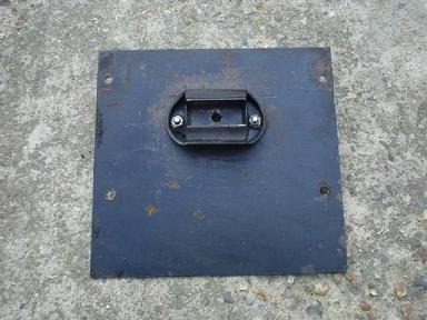 |
Gearbox
Mount The original gearbox mounting was a little too inefficient for my liking and I found it impossible to get the height spot on. So, with a type 9 gearbox mounting block from Westfield cars and a piece of 3mm steel plate I put together this to replace the previous frame mount. |
|
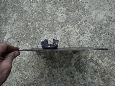 |
Gearbox
Mount This is the same plate shown in profile. As you can see, it shows the plate and the vertical position of the mount. A further advantage of this design is that it replaces the section of floor which was removed and prevents the ingress of muck and road gunge. |
|
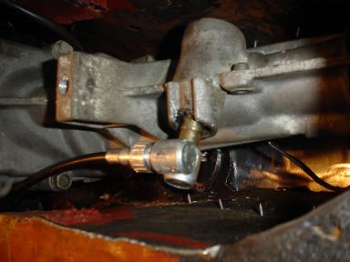 |
Angle
Speedo Drive After busting two speedo cables I decided that the curent routing for the speedo cable was not best. It seems that the angle that it was placed in the gearbox tunnel was far too acute. I looked at running the cable throught the drivers footwell but this just did not feel right. After a suggestion by one of my net friends on the MG BBS, my answer to this was to get a special angle drive made up by Speedy Cables. This shows the angle drive fitted and you will see how it finds a much more efficient route for the cable. |
|
Well, there you have it. If you haven't converted your car yet, do it now. It will probably be the best modification you will do to the car and make motorway cruising far more comfortable. For the adapters talk to James Mather and have a look at his website. |
Drop me a line if you want: mgbob@amphibia.co.uk
A link to my company website Experts in legionella and control of legionnaires disease
|