Bob's
MG Midget Website
Bob's
MG Midget Website| Bob's
MG Midget Website |
An Electronic Fuel Injection Conversion
|
|
The old SU carbs on a Midget are pretty reliable and fairly simple but have some inherent drawbacks in terms of performance. I did try going for Weber 40's but these come with their own difficulties with tuning and low speed running. I toyed with engine swaps and the K series conversions but wrote off the idea due to cost. Then I got to thinking "Wouldn't it be good if you could fit a modern EFI system to an original engine?". So what can I do? None of the ECU's fitted to modern engines would suit an old 1500 Triumph engine designed in the 1950's without serious electronic modification. What I really needed was a completely mappable system that can be tuned to suit anything. I looked at the Emerald systems and the Jenvey systems but although very well engineered, these work out very expensive and would total to around £1500 to £2000 for a system to fit my car! Besides, they are far too sophisticated for what I needed. ..... and then I found the Megasquirt website.
This is a simple efi system designed by two guys in the US by the names of Bruce Bowling and Al Grippo. The concept of this is to provide enough info to allow people to build the system themselves from scratch by way of a shared knowledge base of some very clever engineers. So this is how I went about the job of putting the system together. |
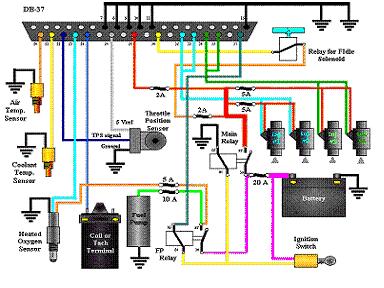 |
The
System The whole system is laid out in this picture showing the whole of the fuel and wiring layout. The 37 pin D-Sub plug is the main connection to the fuel system and sensors on the car. |
|
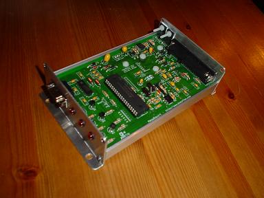 |
ECU
(The Brain) Every EFi system needs an electronic control unit and for the Megasquirt system, this is it. It took me about 8 hours to build and test it in total but was worth it for the final result. Much thanks to Bill Shurvinton who supplies the kits in the UK. Please email me if you would like to contact him and I will forward your details. |
|
 |
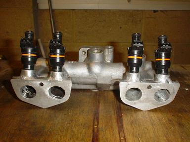
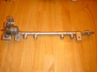
Injectors The business end of the system. A fuel pressure regulator is mounted on the end of the rail which is originally from a Volvo 240 Turbo. The injectors are from a Rover 216 which should provide the right amount of petrol for around 100-110bhp, my eventual target out of the little 1500. |
|
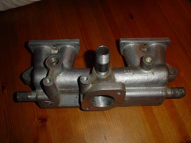 |
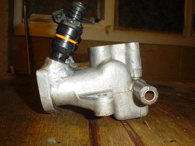
Manifold This manifold is from an American spec Midget 1500 using a 1.5" Stromberg. It is ideal for my purposes as it perfect for mounting a single throttle body. At 38mm the inlet is somewhat small but can be opened up quite a bit to fit the 55mm throttle body to be fitted. The injectors will be fitted into the manifold as close to the head as possible so that the fuel can be squirted direct into the ports on top of the valve heads. This should maximise the low speed throttle response. |
|
 |
Throttle
Body This is from a Mondeo V6 ST24 and measures 55mm at the butterfly and 60mm at the inlet. I have smoothed it off and tapered the inlet to form a bellmouth. |
|
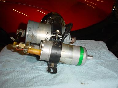 |
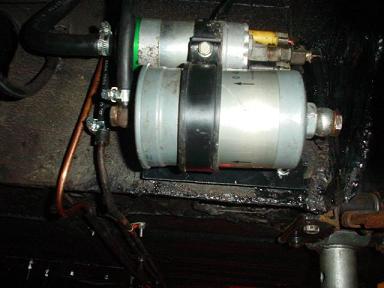
Fuel
delivery This pump and filter assembly is from a Volvo 740. It fits the bill nicely as it will produce 3 bar+ and is a neat package to bolt up under the car. A swirlpot may be needed but for the meantime I shall just pump it straight up to the fuel rail. |
|
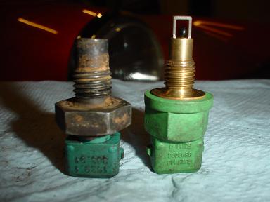 |
Sensors On the left is a water temperature sender and on the right is a manifold air temperature sender. These will tap into the right spots and provide the right feedback for the ECU. Both taken from a VW. |
|
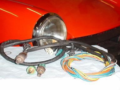 |
Wiring The Bosch ECU wiring loom comes from the same volvo as the fuel rail. It needs some serious splicing but will allow everything to be connected up. The lambda sensor is the exception which came from a Rover 820 in A1 condition. |
|
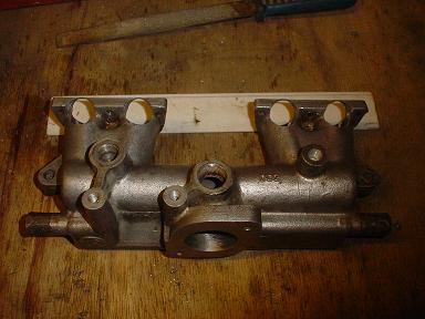 |
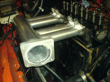
Manifold
prepared The manifold after it had been machined to take the injectors. Gaping great 'oles in the alluminium were a bit offputting but necessary to fit the pockets to be welded in. |
|
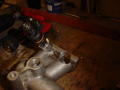 |
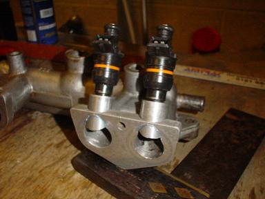
Injectors
2 Using some old injectors for testing, this shows the general arrangement of an injector placed in the machined holes. It is almost 45° to the gasket face and as sharp an angle as possible without fouling the connections needed, of course, it is still yet to be welded up so the fun has not really started. |
|
 |
Injectors
3 |
|
 |
Injectors
4 |
|
 |
Injectors
5 |
|
 |
Fuel
Rail Design 1 |
|
 |
Fuel
Rail Design 2 |
|
 |
Fuel
Rail Design 3 |
|
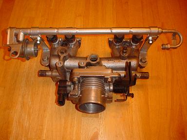 |
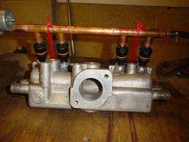
Completed
Manifold System |
|
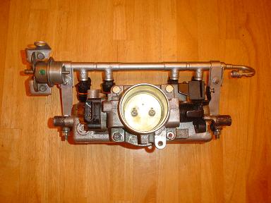 |
Completed
Manifold System (Continued) |
|
 |
Injector
Pump Fitted |
|
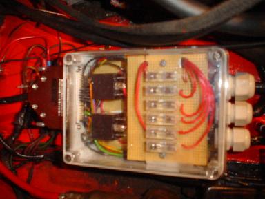 |
Relay
Box |
|
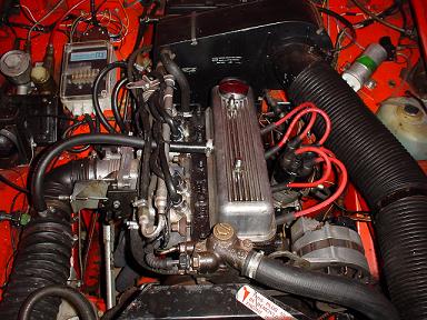 |
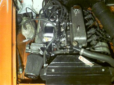
Engine
Bay as Fitted Click on the picture to see a video of the engine running. (Needs Quicktime Player)
|
|
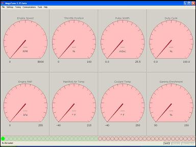 |
Megatune |
|
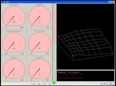 |
VE
Tuning |
|
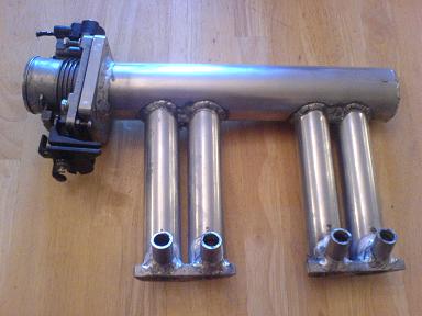 |
A
New Manifold |
|
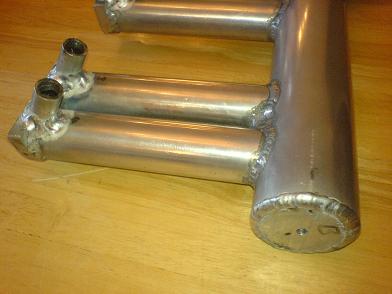 |
Injectors
and Runners |
|
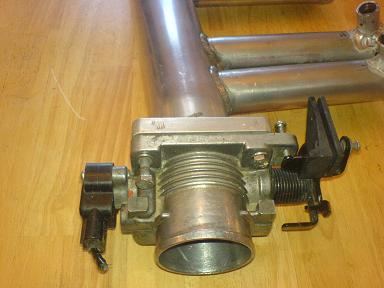 |
Throttle
Body |
|
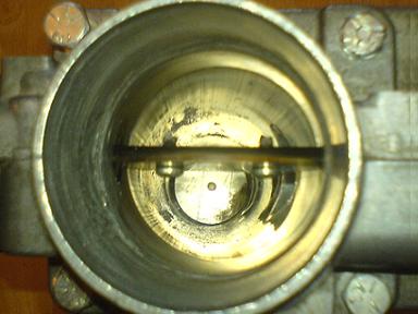 |
Down
the Breathing Hole |
|
 |
First
Fit | |
 |
As Installed | |
|
That's about it for now, I am carrying on with the design as I go. Drop me a line if you want: mgbob@amphibia.co.uk For more information on these systems check out the Megasquirt web site |
A link to my company website Experts in legionella and control of legionnaires disease |